WELCOME TO OUR PROJECTS PAGE
Here you will find all informations of our ongoing projects, either in developing phase or ready prototypes. You can find descriptions and purpose of each board we are working on. Goal here is to make an easy prototype product that can be used either as a power bank or a DIY project at the first stage.
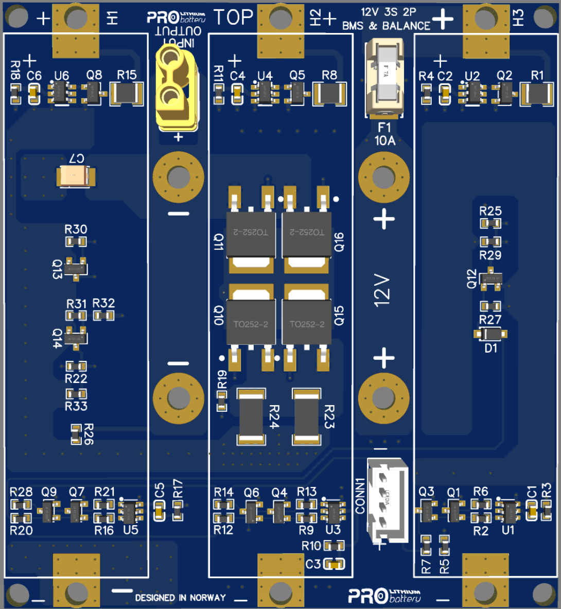
12.6V 3S-2P V. 1.0 BMS
This is the first 12v module developed with a basic BMS integration and a passive balance function. The board is a prototype test module and is ment for study only.
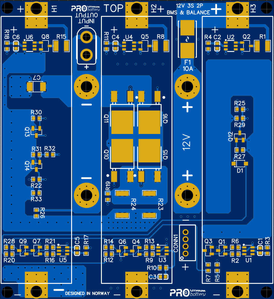
ARCHITECTURE V. 1.0
The test module is designed to connect three battery cells (18650) in series and two in parallel (both sides of the board) with a 10A fuse as a max discharge output per board.
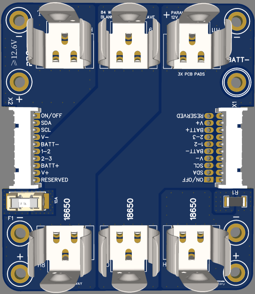
12.6V 3S-2P V. 2.0 BLANK
The second version has an improved designed with different cells holders (steel srping clips) and additional connection points to enable more connection options.
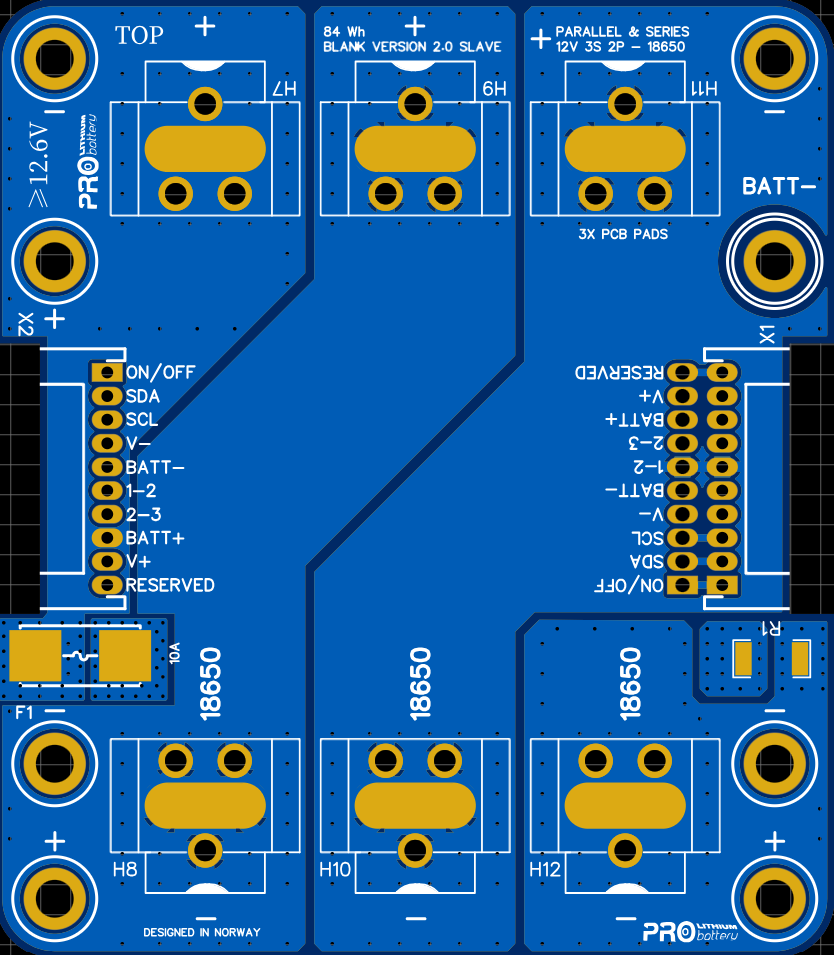
ARCHITECTURE V. 2.0
The architecture of the V. 2.0 Blank board is based on V.1.0, with layout improvments and communication an connection points. The blank version is ment to lower the total costs.
VERSION 2.0 ARCHITECTURE & STRUCTURE
To have a better understanding of what is our goal in version 2.0 is to develop a small (palm size) and compact battery module that serves multipurposes (as a power bank for example). The reason why we call it battery module is because of it’s interconections capabilities. The module can be stacked either on top of each other or side ways, to increas voltage or overall capacity.
V 2.0 MULTIPURPOSE
Mission here is to increase and maximize the purpose of the battery module, in order to achive this we have added key elements into board designed. 8 connection points, (3.2mm hole – 3M screw or standoff) 4 on each side of the board. The total connections gives us the options to parallel the board with other or to connected them in series (on top or side ways) The both 10pins connectors that are on each side, gives us the communication capability between each other for each board connected.
V 2.0 CONNECTIVITY
The best way to interconnect with each board is to use aluminium standoffs and screws in different lenght. This method is used to connected on top of each other (stackable). To connect side ways, we have designed a bus BAR PCB (printed circuit board) that can be connected between two boards side by side.
V 2.0 TOTAL SYSTEM OF SIX BOARDS
Wy six boards? each board has an unique purpose that can connect to each other to give different advantages and options for the user.
1. BLANK BOARD
The blank board is designed to be a ”dummy” board to lower the total costs and add more capacity to the system. The blank board can be controled and monitored by the other boards.
Examiner julius casino fr sous différents angles confirme une cohérence de bout en bout du projet. Une page d’historique recense les bonus passés, présents et à venir pour davantage de transparence. Les conseils sont personnalisés et non extraits de réponses automatiques génériques. Les modes de paiement disponibles couvrent un éventail large adapté aux usages francophones contemporains. Les associations partenaires en matière de jeu responsable sont mentionnées en bas de page. Les guides débutants accompagnent les nouveaux venus dans la découverte des règles principales. Les machines orientées thèmes mythologiques, aventures ou explorations cosmiques constituent un sous-genre particulièrement développé. Le mode portrait offre une lisibilité supérieure pour les rouleaux verticaux des slots. Le chat en direct permet d’échanger avec le croupier ainsi qu’avec les autres participants. La taille des polices reste agréable même sur des écrans 4K ou de petite taille. Au cumul des observations, la plateforme se distingue par sa solidité globale.
2. BMS INTEGRATION
The BMS will be integrated on same board structure (blank board) all boards will have same structure as the blank board. The BMS will either be capable to monitor own cells or connected to blank board to safe monitor the battery cells from the blank board/’s.
3. BMS / ARDUINO (Atemega328chip)
This integration enhance the cabapility of the system and connectivity. Can be connected to PC and monitor the battery in real life, adjustments an functions to come.
4. BMS / ARDUINO / WIFI / BLUETOOTH
The remote function and monitoring capability of a small and compact battery module.
5. IOT INTEGRATION
When no internet is provided, can be placed as a stand alone system and be capable of remote adjustments and monitoring.
6. CHARGE AND DISCHARGE FAST MODULE
To give a practice purpose and be able to utilize the prototype product even at a smaller scale.

UNDERWATER BATTERY MODULE V. 1.0
The design is for study purposes as a first version, is inteded to be used in ROV industry (remote operated vehicle).
The test module is a 24V 7S 1P, using high energy density batteries (21700 battery cells). The design is ment to be as compact possible, a modular design to increase capacity (stackable) The battery module is configured from two boards, left side board is top board and right side is the bottom board.
